自动驾驶定位技术-粒子滤波实践
Particle Filter - Kidnapped vehicle project
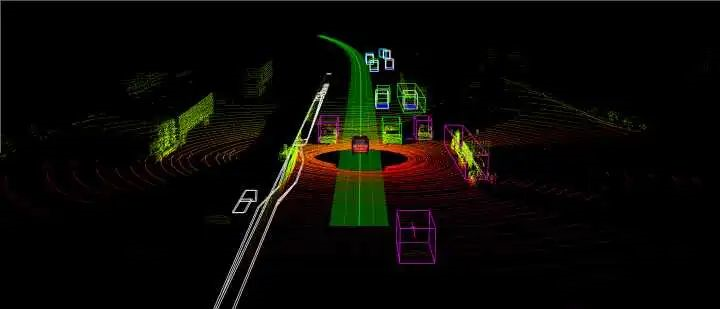
1. Definition of Particle Filter

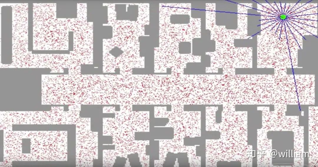
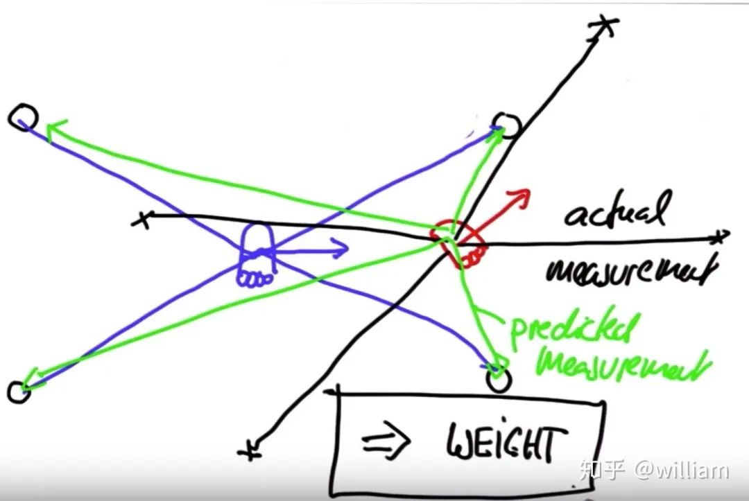
权重(Weights):
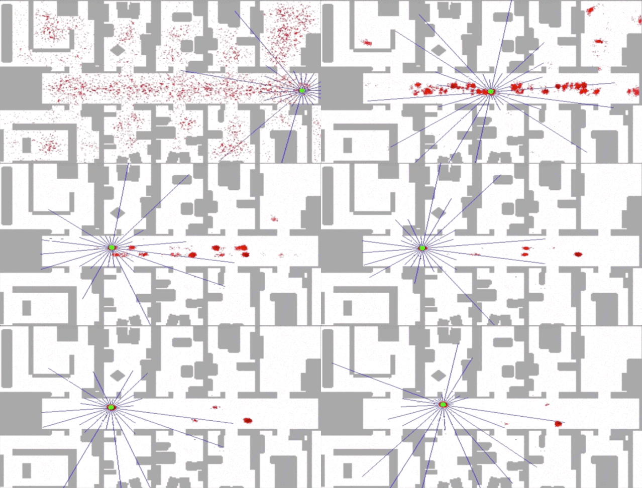
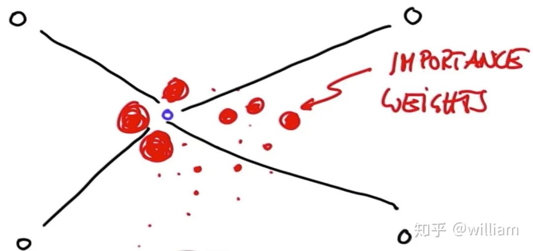
重采样(Resampling)
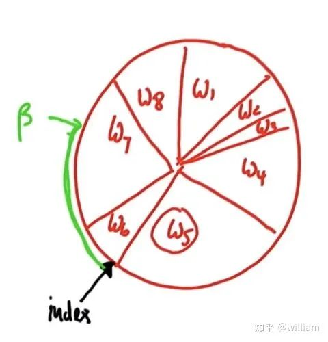
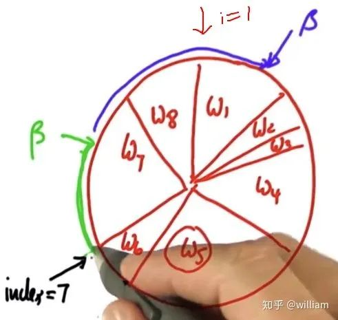
p3 = []
index= int(random.random()*N)
beta=0.0
mw=max(w)
for i in range(N):
    beta +=random.random()*2.0*mw
    while beta>w[index]:
        beta-=w[index]
        index=(index+1)%N
    p3.append(p[index])
p=p3
2. Particle Filters implementation
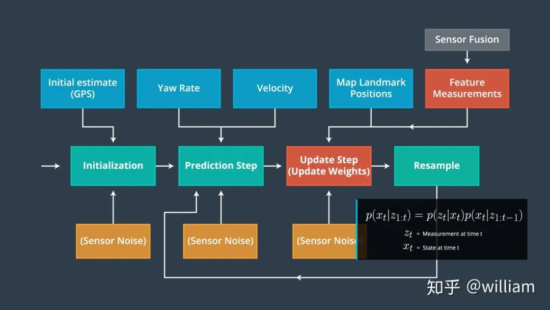
初始化步骤: 我们从 GPS 输入估计我们的位置。在这个过程中的后续步骤将完善这个估计,以定位我们的车辆
预测步骤: 在预测步骤中,我们添加了所有粒子的控制输入(偏航速度和速度)
粒子权重更新步骤: 在更新步骤中,我们使用地图地标位置和特征的测量更新粒子权重
重采样步骤: 在重采样期间,我们将重采样 m 次(m 是0到 length_of_particleArray的范围)绘制粒子 i (i 是粒子index)与其权重成正比。这一步使用了重采样轮技术。
新的粒子代表了贝叶斯滤波后验概率。我们现在有一个基于输入证明的车辆位置的精确估计。
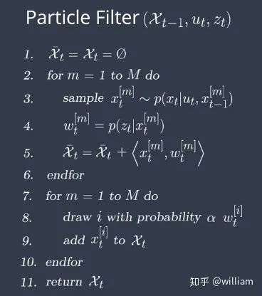
1. 初始化步骤:
void ParticleFilter::init(double x, double y, double theta, double std[]) {
    /**
     * TODO: Set the number of particles. Initialize all particles to
     *   first position (based on estimates of x, y, theta and their uncertainties
     *   from GPS) and all weights to 1.
     * TODO: Add random Gaussian noise to each particle.
     * NOTE: Consult particle_filter.h for more information about this method
     *   (and others in this file).
     */

    if (is_initialized) {
        return;
    }
    num_particles = 100;  // TODO: Set the number of particle

    double std_x = std[0];
    double std_y = std[1];
    double std_theta = std[2];

    // Normal distributions
    normal_distribution dist_x(x, std_x);
    normal_distribution dist_y(y, std_y);
    normal_distribution dist_theta(theta, std_theta);

    // Generate particles with normal distribution with mean on GPS values.
    for (int i = 0; i < num_particles; ++i) {
        Particle pe;
        pe.id = i;
        pe.x = dist_x(gen);
        pe.y = dist_y(gen);
        pe.theta = dist_theta(gen);
        pe.weight = 1.0;
        particles.push_back(pe);

    }
    is_initialized = true;
}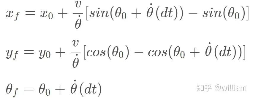
for (int i = 0; i < num_particles; i++) {
       if (fabs(yaw_rate) >= 0.00001) {
           particles[i].x  += (velocity / yaw_rate) * (sin(particles[i].theta + yaw_rate * delta_t) - sin(particles[i].theta));
           particles[i].y += (velocity / yaw_rate) * (cos(particles[i].theta) - cos(particles[i].theta + yaw_rate * delta_t));
           particles[i].theta += yaw_rate * delta_t;
       }
       else {
           particles[i].x += velocity * delta_t * cos(particles[i].theta);
           particles[i].y += velocity * delta_t * sin(particles[i].theta);
       }
       // Add noise
       particles[i].x += disX(gen);
       particles[i].y += disY(gen);
       particles[i].theta += angle_theta(gen);

   }
3. 更新步骤:
Transformation
Association
Update Weights
转换 (Transformation)
我们首先需要将汽车的测量数据从当地的汽车坐标系转换为地图上的坐标系。
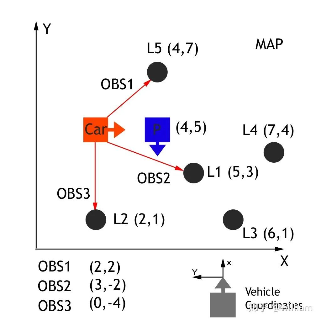
通过传递车辆观测坐标(xc 和 yc)、地图粒子坐标(xp 和 yp)和我们的旋转角度(- 90度) ,通过齐次变换矩阵,车辆坐标系中的观测值可以转换为地图坐标(xm 和 ym) 。这个齐次的变换矩阵,如下所示,执行旋转和平移。

矩阵乘法的结果是:

 double x_part, y_part, x_obs, y_obs, theta;
  double x_map;
 x_map = x_part + (cos(theta) * x_obs) - (sin(theta) * y_obs);
  double y_map;
 y_map = y_part + (sin(theta) * x_obs) + (cos(theta) * y_obs);
联系 (Association )
联系问题是在现实世界中地标测量与物体匹配的问题,如地图地标. 我们的最终目标是为每个粒子找到一个权重参数,这个权重参数代表这个粒子与实际汽车在同一位置的匹配程度。
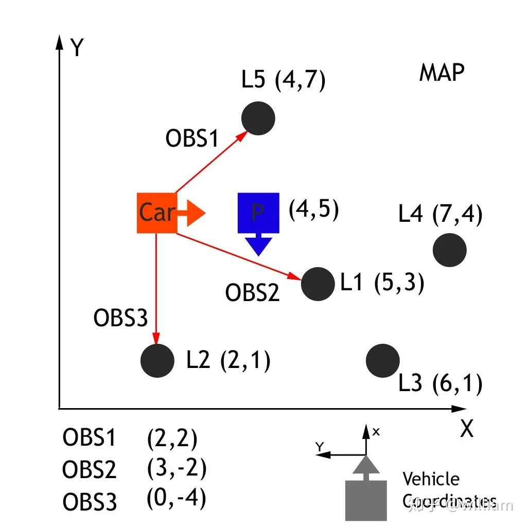
现在已经将观测值转换为地图的坐标空间,下一步是将每个转换后的观测值与一个地标识符关联起来。在上面的地图练习中,我们总共有5个地标,每个都被确定为 L1,L2,L3,L4,L5,每个都有一个已知的地图位置。我们需要将每个转换观察 TOBS1,TOBS2,TOBS3与这5个识别符之一联系起来。为了做到这一点,我们必须将最接近的地标与每一个转化的观察联系起来。
TOBS1 = (6,3), TOBS2 = (2,2) and TOBS3 = (0,5). OBS1匹配L1,OBS2匹配L2,OBS3匹配L2或者L5(距离相同)。
下面的例子来解释关于数据关联的问题。
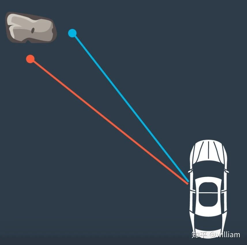
在这种情况下,我们有两个激光雷达测量岩石。我们需要找出这两个测量值中,哪一个与岩石相对应。如果我们估计,任何测量是真实的,汽车的位置将根据我们选择的测量是不同的。也就是说,根据路标选择的不同, 最终确定的车辆位置也会不同。
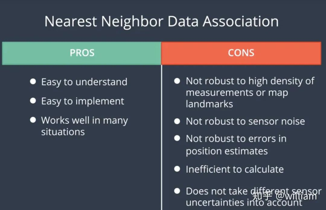
由于我们有多个测量的地标,我们可以使用最近邻技术找到正确的一个。
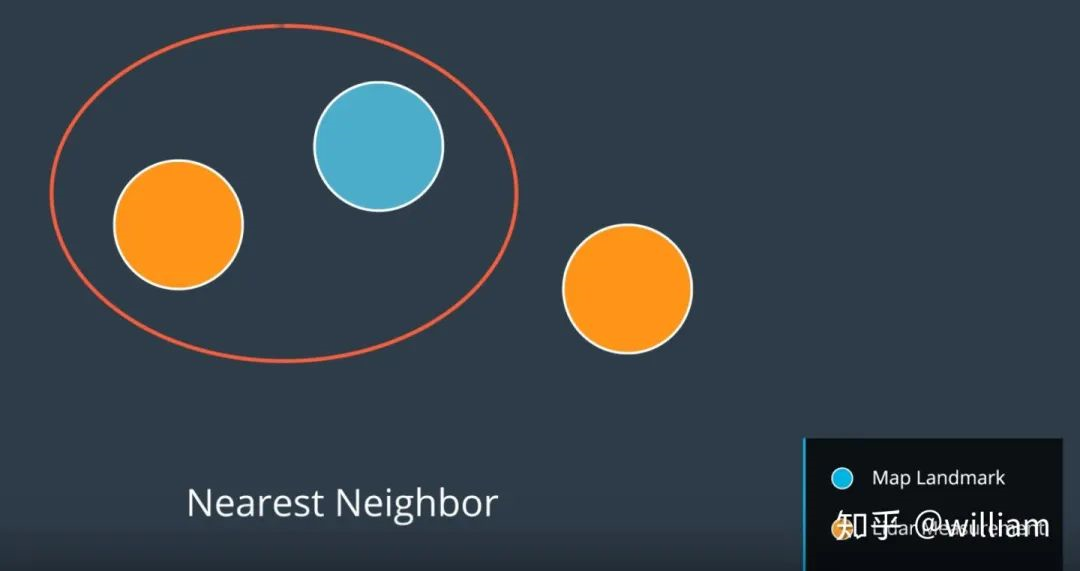
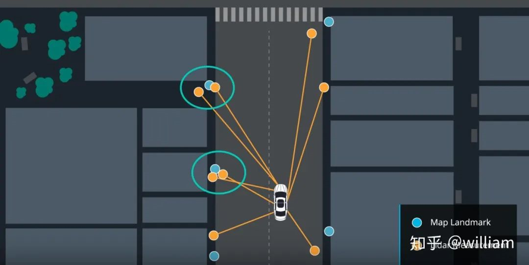 在这种方法中,我们将最接近的测量作为正确的测量。
更新权重 (update weights)
现在我们已经完成了测量转换和关联,我们有了计算粒子最终权重所需的所有部分。粒子的最终权重将计算为每个测量的多元-高斯概率密度的乘积。
多元-高斯概率密度有两个维度,x 和 y。多元高斯分布的均值是测量的相关地标位置,多元高斯分布的标准差是由我们在 x 和 y 范围内的初始不确定度来描述的。多元-高斯的评估基于转换后的测量位置。多元高斯分布的公式如下。

备注:x, y 是地图坐标系的观测值,μx, μy是最近的路标的地图坐标。如对于OBS2 (x,y) =(2,2), (μx, μy)= (2,1)
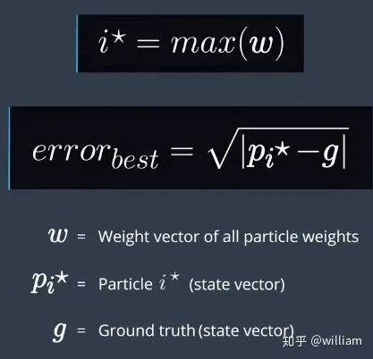
误差计算公式:

void ParticleFilter::updateWeights(double sensor_range, double std_landmark[],
                                   const vector &observations,
                                   const Map &map_landmarks) {
    /**
     * TODO: Update the weights of each particle using a mult-variate Gaussian
     *   distribution. You can read more about this distribution here:
     *   https://en.wikipedia.org/wiki/Multivariate_normal_distribution
     * NOTE: The observations are given in the VEHICLE'S coordinate system.
     *   Your particles are located according to the MAP'S coordinate system.
     *   You will need to transform between the two systems. Keep in mind that
     *   this transformation requires both rotation AND translation (but no scaling).
     *   The following is a good resource for the theory:
     *   https://www.willamette.edu/~gorr/classes/GeneralGraphics/Transforms/transforms2d.htm
     *   and the following is a good resource for the actual equation to implement
     *   (look at equation 3.33) http://planning.cs.uiuc.edu/node99.html
     */
    double stdRange = std_landmark[0];
    double stdBearing = std_landmark[1];
    // Each particle for loop
    for (int i = 0; i < num_particles; i++) {
        double x = particles[i].x;
        double y = particles[i].y;
        double theta = particles[i].theta;
//        double sensor_range_2 = sensor_range * sensor_range;
        // Create a vector to hold the map landmark locations predicted to be within sensor range of the particle
        vector validLandmarks;
        // Each map landmark for loop
        for (unsigned int j = 0; j < map_landmarks.landmark_list.size(); j++) {
            float landmarkX = map_landmarks.landmark_list[j].x_f;
            float landmarkY = map_landmarks.landmark_list[j].y_f;
            int id = map_landmarks.landmark_list[j].id_i;
            double dX = x - landmarkX;
            double dY = y - landmarkY;
            /*if (dX * dX + dY * dY <= sensor_range_2) {
                inRangeLandmarks.push_back(LandmarkObs{ id,landmarkX,landmarkY });
            }*/
            // Only consider landmarks within sensor range of the particle (rather than using the "dist" method considering a circular region around the particle, this considers a rectangular region but is computationally faster)
            if (fabs(dX) <= sensor_range && fabs(dY) <= sensor_range) {
                validLandmarks.push_back(LandmarkObs{id, landmarkX, landmarkY});
            }
        }
        // Create and populate a copy of the list of observations transformed from vehicle coordinates to map coordinates
        vector transObs;
        for (int j = 0; j < observations.size(); j++) {
            double tx = x + cos(theta) * observations[j].x - sin(theta) * observations[j].y;
            double ty = y + sin(theta) * observations[j].x + cos(theta) * observations[j].y;
            transObs.push_back(LandmarkObs{observations[j].id, tx, ty});
        }

        // Data association for the predictions and transformed observations on current particle
        dataAssociation(validLandmarks, transObs);
        particles[i].weight = 1.0;

        for (unsigned int j = 0; j < transObs.size(); j++) {
            double observationX = transObs[j].x;
            double observationY = transObs[j].y;
            int landmarkId = transObs[j].id;

            double landmarkX, landmarkY;
            int k = 0;
            int nlandmarks = validLandmarks.size();
            bool found = false;
            // x,y coordinates of the prediction associated with the current observation
            while (!found && k < nlandmarks) {
                if (validLandmarks[k].id == landmarkId) {
                    found = true;
                    landmarkX = validLandmarks[k].x;
                    landmarkY = validLandmarks[k].y;
                }
                k++;
            }
            // Weight for this observation with multivariate Gaussian
            double dX = observationX - landmarkX;
            double dY = observationY - landmarkY;
            double weight = (1 / (2 * M_PI * stdRange * stdBearing)) *
                            exp(-(dX * dX / (2 * stdRange * stdRange) + (dY * dY / (2 * stdBearing * stdBearing))));
            // Product of this obersvation weight with total observations weight
            if (weight == 0) {
                particles[i].weight = particles[i].weight * 0.00001;

            } else {
                particles[i].weight = particles[i].weight * weight;
            }
        }
    }
}
重新采样步骤 (Resample step)
重采样技术是用于从旧粒子中随机抽取新粒子,并根据重要权重按比例进行置换。重采样后,权重较大的粒子可能会停留下来,其他粒子可能会消失。这是粒子过滤器的最后一步。
项目的最终重采样代码:
void ParticleFilter::resample() {
    /**
        * TODO: Resample particles with replacement with probability proportional
        *   to their weight.
        * NOTE: You may find std::discrete_distribution helpful here.
        *   http://en.cppreference.com/w/cpp/numeric/random/discrete_distribution
        */
    // Get weights and max weight.
    vector weights;
    double maxWeight = numeric_limits::min();
    for (int i = 0; i < num_particles; i++) {
        weights.push_back(particles[i].weight);
        if (particles[i].weight > maxWeight) {
            maxWeight = particles[i].weight;
        }
    }
    uniform_real_distribution dist_float(0.0, maxWeight);
    uniform_real_distribution dist_int(0.0, num_particles - 1);
    int index = dist_int(gen);
    double beta = 0.0;
    vector resampledParticles;
    for (int i = 0; i < num_particles; i++) {
        beta += dist_float(gen) * 2.0;
        while (beta > weights[index]) {
            beta -= weights[index];
            index = (index + 1) % num_particles;
        }
        resampledParticles.push_back(particles[index]);
    }
    particles = resampledParticles;

}
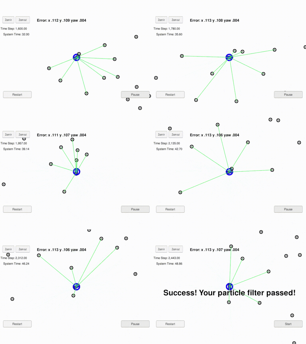
3. Project Demo

- 用户评论


